What is flex circuit?
- Flex Plus Tech team
- May 9, 2024
- 3 min read
Updated: Mar 10
Flex circuit, commonly referred to as flexible circuit boards or flex PCB, has a significant influence on electronic design and manufacturing. In the field of modern electronics, flexibility and adaptability have become more and more important. As demands for smaller, lighter, and more versatile devices increase, traditional rigid circuit boards often fall short.
Understanding Flex Circuit
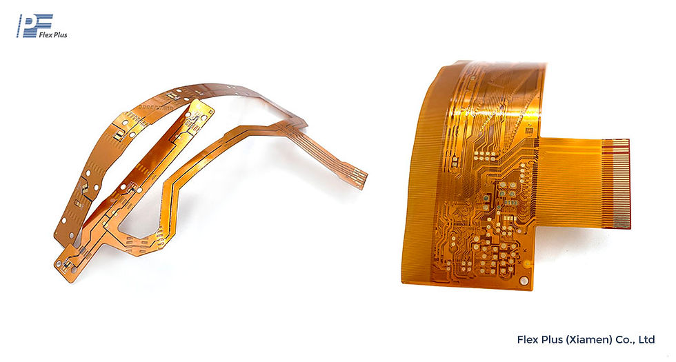
Flexible circuit boards are different from traditional PCBs. They are composed of flexible substrates, typically polyimide or polyester, which enable them to bend, twist, and conform to the shape of the device. This flexibility opens up a world of possibilities for designers and engineers, allowing for the creation of compact, lightweight, and durable electronic products.

Flex PCB Technology
Flex PCB technology includes a series of techniques and processes towards the flex PCB fabrication. At its core, flex PCB technology uses the unique properties of flexible substrates to design circuitry that can withstand bending and flexing without sacrificing performance. Key components of flex PCB technology include:
Substrate Materials: Polyimide and polyester are the primary base materials used in flexible PCBs because of their wonderful thermal stability, mechanical strength, and flexibility.
Conductive Traces: Conductive traces are typically made of copper and are patterned onto the flexible substrate using techniques such as etching or screen printing.
Flex circuit Coverlay: Coverlay, or solder mask, is a protective layer applied over the conductive traces to insulate them and provide mechanical protection.
Adhesive Materials: Adhesive materials are used to bond layers of flexible substrates together and attach components to the flex PCBs.
Flex PCBs are categorized based on their design and application:
One layer Flex Circuits: Feature conductive traces on one side of the substrate, suitable for simple, low-density applications.
Two-layer Flex Circuit: Offers conductive traces on both sides, interconnected by plated-through holes, accommodating more complex designs.
Multilayer Flex PCBs consist of multiple layers of conductive traces bonded together, providing high-density interconnections for sophisticated applications.
Rigid-Flex Circuits: Combine rigid and flexible PCBs into a single unit, offering a balance between structural support and flexibility.
The versatility of flex PCB lends itself to a wide range of applications across various industries. Some notable applications include:
Consumer Electronics: Flex PCBs are used in smartphones, tablets, wearables, and other consumer electronics.
Automotive: In the automotive industry, flex PCBs are employed in dashboard displays, lighting systems, and engine control units, where space constraints and vibration resistance are critical.
Medical Devices: Flex PCBs are very important in medical devices such as hearing aids, CT images, endoscopes, and diagnostic equipment, where flexibility and reliability are paramount.
Aerospace and Defense: In aerospace and defense applications, flex PCBs are utilized in avionics, radar systems, etc., where lightweight and ruggedized electronics are essential.
Manufacturing Process of Flex Circuit Board
The manufacturing process of flex PCB involves several steps, each of which is critical to ensuring that the final product meets the required specifications:
Substrate Preparation: The flexible substrate material is prepared by coating it with adhesive and copper foil and then laminating it together to form a copper-coated laminate.
Circuit Patterning: Using photolithography or laser ablation, the conductive lines and component pads are patterned onto the substrate.
Etching: Chemical etching is used to remove excess copper from the substrate, leaving the desired conductive trace.
Coverlay Application: A coverlay film is applied over the conductive traces to insulate them and protect them from environmental factors.
Component Assembly: Components such as integrated circuits, resistors, and capacitors are mounted onto the Flex PCB by using surface mount technology (SMT) or through-hole technology (THT).
Testing and Inspection: The flex PCB undergoes rigorous testing and inspection to ensure it meets quality standards and functions correctly.
Advantages of Flex PCBs
Flexible PCBs offer several distinct advantages over traditional rigid PCBs:
Space and Weight Savings: Their ability to conform to various shapes allows for more compact and lightweight designs, which is crucial in applications like wearable technology and aerospace.
Enhanced Durability: Their resistance to vibrations and mechanical stresses makes them ideal for applications subject to movement and environmental challenges.
Design Flexibility: Facilitate innovative designs that integrate multiple functions within a single, flexible unit, reducing the need for multiple rigid boards and connectors.
Future Outlook
As technology continues to evolve, the future of Flex PCBs looks promising. Advancements in materials science, manufacturing processes, and design techniques will further enhance the capabilities of flexible circuit boards, enabling smaller, more powerful, and more resilient electronic devices. With their unparalleled flexibility and adaptability, flex PCBs will remain at the forefront of electronics innovation for years to come.
Flex PCB, represents a paradigm shift in electronic design and manufacturing. From consumer electronics to automotive and aerospace applications, flex PCBs are changing the way we think about electronics.
Comentarios